Network Intent#
The request was a new VLAN for a tenant service, on 60 switches across two buildings. An engineer filled in the service record by hand: VLAN ID 4192, gateway 10.2.30.283. Both were typos, one digit each. The tenant’s VLAN was 4092 and the gateway was 10.2.30.238.
Neither field was checked, because neither field had ever been anything but free text. Both had started life as columns in a spreadsheet, and a spreadsheet holds no opinion about what a VLAN ID is. Review passed in four minutes: the record looked like every other VLAN request that year, and both values look right at a glance, which is what a transposed digit does. The templates rendered them without comment, because a template substitutes, it does not judge.
The maintenance window opened at 02:00, and every switch refused the first line of the configuration, each in its own words. One vendor reported an invalid input, the second that the VLAN was out of range, the third a syntax error and a line number. Nothing deployed, which was the best news of the night. The engineer spent 50 of the 90 minutes reading three different parser messages before tracing them back to a field in a form, then fixed two digits and re-ran. The service went live at 03:10.
Two things would have prevented that night, and they are the two halves of this chapter. The weaker one is a schema: a VLAN ID is an integer between 1 and 4094, an address is an address, and a record that breaks either rule cannot be saved. The stronger one is to stop asking an operator for the value at all.
Every automation system starts with one question: What am I actually going to do? When you deploy a firewall rule, add an IP address, or configure a VLAN, you’re doing it based on some representation of intent. That representation is your source of truth: the single, reliable version of what your network should look like.
I use “Source of Truth” and “Intent” interchangeably. They represent the same concept. This chapter covers the data: what the intent holds, and what makes a value valid. Chapter 5 covers the system that stores it, serves it, and decides which source owns each value.
Without a reliable source of truth, network operations become a mess of tribal knowledge. Engineers disagree on what’s deployed. Spreadsheets contradict what’s actually running. Two different automation systems make conflicting changes to the same device. When something breaks, you’re left doing archaeology: “Why was this configured this way? Who approved it? When did it change?”
Having one is not enough, though, as the opening story shows. A record that nothing checks is just a faster way to distribute a mistake.
This chapter looks at the data itself: what belongs in your intent, at which level of abstraction, and what has to be true of a value before automation is allowed to act on it. Get this part wrong and nothing built on top of it can be right, however good the machinery around it is.
The first stop is to define what the Source of Truth is for, and where its boundaries fall.
Fundamentals#
The SoT serves as the north star of the whole network automation system. To make that possible, it has to deliver on a few crucial points:
Capture everything you need, at different levels. Represent and store the full intent definition of your network (at the level of detail you need): from the higher business level (“add a new branch” or “set up an MPLS service”), to agnostic technical data (IP addresses, circuits, device specs, credential references, maintenance windows), and finally concrete configuration artifacts per-device. The data may be very diverse. Moreover, it should support the data lifecycle, and include not just what’s running today, but what you’ve planned and what you’re retiring. In short, the SoT should provide enough data to let you rebuild your network from scratch.
Maintain data integrity, allow flexible representation. Validate everything: check that data types are right, relationships make sense, VLANs are in valid ranges, IP addresses don’t duplicate. Track who changed what and when. Let people approve major changes before they stick. If something goes wrong, you can roll back. Your automation needs to trust that the data is accurate, because bad data leads to bad network state and outages.
Support people working in parallel without stepping on each other. Multiple teams should be able to propose changes at the same time. Changes get grouped into atomic bundles: either they all go in or they all fail, no halfway states. You can test changes in a staging area before they go live. For big migrations, you can branch off, do your work, and merge back. You always know which intent is being used now versus what’s being proposed.
Allow people and machines to access the data easily and securely. Your system needs Application Programming Interface (API)s (Representational State Transfer (REST), GraphQL) so automation can get and modify data. It needs a web UI and Command Line Interface (CLI) so humans can browse and edit, too. Everyone needs solid access controls so they only see what they should. You can have a hundred automation workflows running at the same time, dozens of staff editing data, and external systems syncing in, and it all should stay consistent and responsive.
Embrace data consolidation from other systems. You may already have asset management for hardware, IP systems for addresses, or circuit providers for connectivity. Don’t duplicate that. Instead, sync it in. Make clear rules about which system owns which data. Keep everything in sync both ways. This means you get a unified view of everything without reinventing the wheel.
Before diving into implementation details, it’s important to understand what the source of truth is responsible for, and what it is not, so its boundaries stay clear.
What’s in scope
The source of truth manages all intent data: the complete definition of what your network should look like. This includes production configurations, staging environments, development branches, and test scenarios. Everything that describes “what you want” lives here.
What’s out of scope
The source of truth doesn’t do several things that might seem related:
Observability data: The source of truth doesn’t store metrics, logs, or runtime state. However, it does define the expectations you’ll compare against, like threshold values for alerts or baseline performance numbers. The actual observability data lives elsewhere (covered in Chapter 7).
Network interaction: The source of truth doesn’t talk to devices or push configurations. It provides the intent the Executor needs, as rendered artifacts or as technical-layer data, but doesn’t execute it. That’s the Executor’s job (Chapter 6).
Orchestration logic: The source of truth doesn’t define the sequence of steps or workflows for deploying changes. It defines the intended final state. How you get there (which devices first, what validation steps, rollback procedures) belongs to the Orchestrator (Chapter 8).
The source of truth is the authoritative answer to “what should the network look like?” Everything else in your automation system (execution, monitoring, orchestration) references this truth to do its job. When reality drifts from intent, the source of truth tells you what reality should become.
There is a second, less obvious payoff. Automation is rarely about building something once; networks move continuously from one state to the next. Moving from state A to state B is a completely different problem when state A is written down. If both the current intent and the new intent are known, automation can compare them, work out what actually has to change, and touch only that. Without a defined starting point, every change begins with rediscovering what is already out there. This is what makes automation repeatable instead of merely scripted.
Those five goals split in two, and so does the material. This chapter is the data: what the intent holds, how it layers, and what makes a value valid. Chapter 5 is the machinery around it: the history you can roll back to, teams working in parallel without colliding, access for people and machines, and the rule that decides which system owns each value. The goals and the boundaries set out above hold for both chapters; the next one picks up where this one stops.
So start with the data. Everything else is built on top of it.
Data in Scope#
Data sounds very generic, and it actually is. The intent data that establishes the source of truth exists at different levels, each one with a different purpose. Generally speaking, there are three layers, from more abstract to more concrete, as you can see in the following figure:
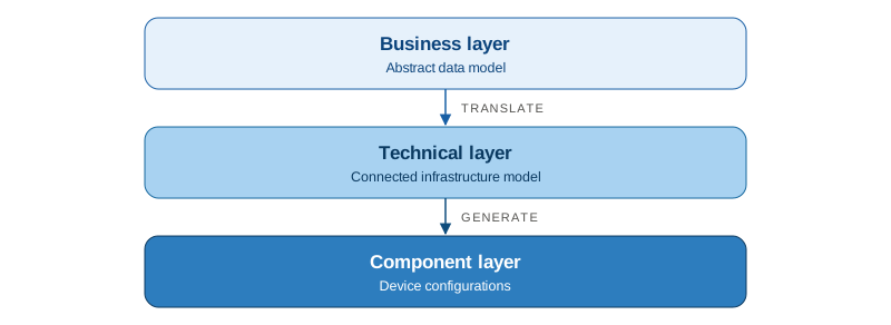
- Business layer: covers the high-level abstractions that improve usability, hiding lower-level details that may not be relevant for some personas. For example: “set up an MPLS L3VPN for branch X”.
- Technical layer: defines the infrastructure data your network requires, in agnostic terms (not vendor-specific). For example: “BGP AS 65001, route targets 65001:100, interface admin status, etc.”.
- Component layer: the final per-device configuration artifact needed to change the configuration state of a network device or service. For example: “interface xe-0/0/0; unit 100;…”. The Intent block owns it, though the code that produces it can run in the Source of Truth or inside the Executor, as the Component Layer section explains.
A good data intent strategy connects these layers. You can start at a business level, then generate technical data automatically. But you don’t always need all three layers: it depends on what you’re building.
There is a second way to slice the same question: not by level of abstraction, but by who is asking. Different people and systems meet the same intent at different altitudes.
- A network engineer works in the technical layer: interfaces, IP addresses, routing attributes, VLANs. They read the component layer to review what will reach a device, and they author the templates that produce it, but they should not be editing per-device artifacts by hand.
- A service or business owner only wants to say what service is needed, where, and with what characteristics. That is the business layer.
- An automation workflow or AI agent needs a structured, predictable view it can act on, or sometimes just the finished configuration artifact to push.
Thinking in personas tells you what data is needed, by whom, and at what level of detail. It also stops you from exposing the full 500-field device object to someone who needs five fields of it. The goal is not a separate copy of intent per audience, which is how you end up with five sources of truth; it is one intent with the right view over it for each consumer. The Data Consumption section covers how to build those views.
Of the three data layers, let’s start with the heart: the technical layer.
Technical Layer#
The technical layer is the model of what the network is actually made of: devices, interfaces, VLANs, prefixes, circuits, and much more. The modeled data is crucial: it determines what you can represent and how easily you can work with it. As George Box noted: “All models are wrong, but some are useful”. There’s no perfect model that works for everyone, but you still need one. In my experience, data modeling is more art than science, but certain patterns show up consistently across successful projects.
The first pattern is the set of data families that show up in most networks, which the next section works through.
Data Families#
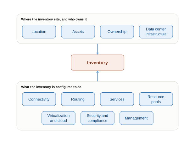
Comprehensive Source of Truth implementations typically model different data families, but the Inventory is the cornerstone. It defines the objects under management that every other family hangs off, and it takes two forms depending on what you are managing:
- Physical and virtual devices, with whatever identifies each one: name, type, model, platform, and other attributes.
- Cloud services that act as a management unit in their own right, a virtual network for example, with the type of the service and the cloud provider, plus other information.
You may be used to thinking of inventory as devices only. I include here the anchoring cloud services you use to build cloud infrastructure, as another kind of inventory that the other data families reference in the same way.
The families around it fall into two groups. The first describes where the inventory sits and who it belongs to:
- Location: where inventory items are, composed hierarchically: continents, countries, regions, cities, buildings, floors, rooms, whatever matches your actual hierarchy.
- Assets: hardware that has no meaning on its own, only as part of an inventory device, and that nests several levels deep: an expansion module holding cards holding optics. Serial numbers, procurement dates, and warranty terms belong here, on the thing that is actually serialized.
- Ownership: the tenants, users, or accounts a piece of inventory belongs to. This is usually connected to the authentication mechanism.
- Data Center Infrastructure: racks and rack units, power feeds, PDUs and circuits, cooling zones, and the physical cabling and patch panels between them. Relevant when you are building data centers, and safely skipped when you are not.
And, the second group describes what the inventory is configured to do:
- Resource Pools: the ranges you allocate from (e.g., IP prefixes, VLAN IDs, ASNs, DHCP scopes) and the allocations drawn out of them.
- Connectivity: physical circuits (MPLS, Ethernet), virtual tunnels, bandwidth allocations, QoS policies.
- Routing: BGP communities, autonomous systems, routing policies, prefix lists, route targets for L3VPN services.
- Services: logical service definitions (L3VPN, L2VPN, firewall traversal), service-to-device mappings, SLAs.
- Virtualization and Cloud: what runs inside a cloud inventory item: subnets, other services.
- Security and Compliance: access control lists, firewall rules, cloud security, security zones, compliance tags, audit requirements.
- Management: SNMP details, gNMI subscriptions, NTP sources, syslog targets, TACACS+/RADIUS integration.
These families are interdependent, and Figure 4.2 shows how. Everything references the inventory, which is what makes it the cornerstone rather than just the first item on a list: a prefix is assigned to an interface on a device, a service runs across devices, a rack holds them. A well-designed SoT models those relationships explicitly rather than treating each family as an isolated table, and that is something the Data Structure has to facilitate.
As you can see, beyond network-specific data, many other data families are needed: users, locations, or secrets. Not all the data falls into the network domain, but the network intent should connect it consistently even when it does not own everything in one data store.
Sometimes the value stored is just that, a reference rather than the real value. For example, secret credentials should never be stored in a backend that is not designed for them, and never persisted anywhere else. There are two general use cases:
- The credential the Executor or Collector needs to open a session with a device stays a reference end to end: the SoT holds something like
vault://campus/switch-admin, and the Executor resolves it against the vault itself. - A secret that has to appear inside the configuration: a BGP MD5 key, an SNMP community, or a RADIUS shared secret has to reach the device as a real string, so the component layer resolves the reference at render time, injects the value into the artifact it is building, and persists none of it.
People often ask what a network-specific data source like NetBox buys them over a general-purpose one like ServiceNow. In my experience, both can achieve similar outcomes, but a generic system is company-wide, which makes it harder and slower to evolve to represent the network data you need. That slows the network team down before it can use the system for a complete network representation.
Having covered the kinds of data a network needs, the next section gives the general rules for modeling them.
How to model the data#
The families above say what there is to model. These rules decide how, and they hold whichever family you are working in.
Scope the data to your use case, not to everything that exists. The temptation with a fresh SoT is to model the entire network in full fidelity. Resist it. What belongs in scope is whatever your operations actually consume, and that differs sharply by use case:
- A data center build-out needs physical detail: locations, racks, device positions, cable breakouts.
- An edge or backbone network needs every transit and peering session, with enough attributes to form the adjacency.
- Configuration management needs the inventory that lets you open a session at all: management address, platform type, credentials.
- Network monitoring needs to tell a node-facing port from an uplink, and the utilization threshold that applies to each.
Modeling data nobody reads is not free. It costs schema complexity, validation rules, and someone’s attention to keep it accurate; and stale data is worse than absent data, because people trust it once before they stop trusting anything.
Model one address, not two. Nearly every network now carries both address families, and the tempting shortcut is a v4 model and a parallel v6 model. Resist that for the same reason you resist a model per vendor: an interface, a prefix, and a BGP neighbor each need to relate to an address, and if there are two address types then every one of those relationships gets built twice, queried twice, and validated twice. Model a single address object with a family attribute, and let a prefix carry both a v4 and a v6 value where the service is dual-stack. The schema examples later in this chapter accept either family for exactly this reason.
Keep the technical layer vendor-agnostic. This is the constraint that decides whether the layer survives your next hardware refresh. An interface is an interface whichever vendor built the box; model it once, in neutral terms. The moment the technical layer encodes platform syntax, you need a parallel model per vendor, the same intent exists in three places with three chances to disagree, and onboarding a fourth vendor means modeling the network again from scratch. That is a lock-in you built yourself. Vendor specifics are real, but they belong one level down, in the component layer, which turns the agnostic model into each platform’s format.
How granular should your model be? This matters for performance. If you model every interface on every device as a separate object, you end up with 50,000+ objects for a medium network. Queries get slow. Updates become painful. The practical approach: use data templates for common patterns. Say “interfaces 1-40 use this standard template” and only track exceptions. That’s 2 objects instead of 40, queries stay fast, and the component layer still works.
Use transversal classification attributes. All the previous data models have their own particular attributes, but a few classification patterns appear consistently across all network data. Well-designed models include these foundational attributes to keep data manipulation consistent:
- Role: What purpose does this object serve? (core, distribution, access; primary, secondary)
- Status: Is it active, planned, decommissioning, or retired?
- Kind: What type of object is it? (VLAN, device, circuit, service)
The technical layer provides the data models to represent the network data in an agnostic way, but the network infrastructure understands concrete syntax that is very often platform-dependent. So we need to transform it into actual configuration artifacts.
Component Layer#
Network engineers should work, most of the time, at a higher data level rather than with per-device artifacts. But sooner or later, this data needs to be transformed into concrete configuration artifacts. That transformation needs two things: device-specific information from the technical layer, and a transformer that converts it into each platform’s native format, whether CLI, YANG, or a REST API model.
That transformation, or rendering, is the component layer’s mission: turning technical-layer data into each platform’s vendor-specific syntax. The Intent block owns it. Owning it is not the same as hosting it, though, and the end of this section shows the two places the rendering code can run.
Do not confuse this with configuration backups. A backup belongs to the Observability block: it is the configuration actually running, and it does not tell you what your intent is, only what your intent may have been in the past. The component layer produces its artifacts on the fly, from current intent.
The transformation can be implemented in many ways. Jinja2 is a popular choice for CLI-based configuration artifacts (because it’s human-readable, integrated with Python and Ansible), while payload-based ones (REST API, gNMI, etc.) typically rely on data structures built with a programming language.
Templates, like Jinja2, turn abstract intent (“I want a VLAN”) into actual CLI commands. Here’s the key rule: templates contain logic, not data. The template says “use the VLAN ID from the data model, output it here.” The actual VLAN ID comes from the data, not the template. This keeps data portable and testable.
For example, given a data model for interfaces like this:
interfaces:
  - name: Ethernet1
    description: Uplink to core
    enabled: true
  - name: Ethernet2
    description: Server port
enabled: falseAnd this CLI configuration Jinja2 template
# Interfaces
{% for iface in interfaces %}
interface {{ iface.name }}
  description {{ iface.description }}
  {% if iface.enabled %}
  no shutdown
  {% else %}
  shutdown
  {% endif %}
{% endfor %}It generates the following CLI output:
# Interfaces
interface Ethernet1
  description Uplink to core
  no shutdown
interface Ethernet2
  description Server port
shutdownNotice the clear separation of concerns between the data and the configuration artifact. The data is what comes from the technical layer, the template is what the component layer defines, and the configuration artifact is the result.
The exception: invariants belong in the template. The rule above (avoid data in templates) is the general one, and it is worth defending. But not every value in a configuration is data. If every interface in your network runs the same MTU, and no one has ever needed a different one, an
mtuattribute on the interface model buys you nothing: it is a field to populate, validate, and keep consistent across thousands of objects, all to express a constant. Put it in the template instead. The moment one interface does need a different value, a GRE tunnel at 1476 say, it becomes data again, and Listing 4.7 models it that way.
An interesting alternative to Jinja is the CUE declarative configuration language that unifies multiple data functionalities:
- Raw data, like YAML
- Data validation/schema, like JSON Schema (more in the enforcement section)
- Dynamic data generation, like Jinja
CUE treats configuration as typed, composable data with enforced invariants rather than as loosely structured text (like Jinja).
Where the rendering runs#
The example above quietly assumed the rendering happens next to the data, in the Source of Truth. That is one of two places the component layer’s code can run, and real platforms use both, often side by side in the same fleet:
- Render in the Source of Truth. Templates next to the data produce a complete artifact per device. The Executor receives that finished artifact and delivers it. Because the artifact exists before anything touches the network, you can review it, test it without a device, and store it with the change.
- Translate in the Executor. The Executor receives technical-layer data, and a platform module turns it into the device’s syntax at execution time. Declarative resource modules, such as Ansible’s
cisco.ios.ios_vlans, cloud providers in infrastructure-as-code tools, and the device drivers inside network orchestration products all work this way. Someone else maintains the translation, and the module can read the device before deciding what to send.
Neither one moves the responsibility. In both, the component layer does the same job: vendor-agnostic data in, platform syntax out. The technical layer stays the contract, and vendor syntax never flows back up into it. What changes is which tool hosts the code and who maintains it. One tool can implement several functions, and an Executor module that translates is hosting a piece of the Intent block.
| Render in the Source of Truth | Translate in the Executor | |
|---|---|---|
| What reaches the Executor | A rendered artifact | Technical-layer data |
| Who maintains the translation | You, as templates | The module’s author, vendor or community |
| Reviewable before apply | Yes: the artifact itself | Only through the module’s dry-run diff |
| Needs device state | No: it renders the full intended state | Often: it computes the delta against the device |
| Best fit | Interfaces that accept a full replace | Merge-only CLI, cloud APIs, controllers |
| Main risk | Template sprawl as platforms multiply | Behavior tied to a module version you do not control |
To choose, ask one question: does the translation need the device’s current state? Stateless translation, full intended state in and full payload out, needs nothing from the device, so it belongs with the data. It fits any interface that can replace a whole section of configuration, such as NETCONF or gNMI with replace semantics. Stateful translation needs to read the device first. Removing VLAN 412 through a merge-only CLI means sending no vlan 412, and only something that has read the device knows to send it. That belongs in an Executor module.
One rule holds for both: the change is visible before it is applied. With Render in the Source of Truth, the artifact is that evidence. With Translate in the Executor, the module’s dry-run diff is, and Chapter 6 builds that dry-run into the engine. A module that cannot show its diff should not run unattended.
The campus example at the end of this chapter renders in the Source of Truth, because three fields of intent and one template make the layers easiest to see.
So far, with the technical and component layers, you can see that network intent can become extraordinarily complex; think of all the data required to produce your configuration artifacts. But complex data doesn’t have to mean complex interaction. Quite the opposite: we recommend aiming for the simplest possible default interface, one that uses abstraction to translate high-level intent into low-level data.
Business Layer#
When you have 50 devices and 30 VLANs, you can manage them individually: create each VLAN, configure each interface, allocate each IP by hand. It’s tedious but manageable.
When you have 5,000 devices and hundreds of services, manual management is impossible. Adding a new branch office would mean manually specifying 100+ config items per location. The Business Layer solves this: operators describe what they want in business terms (“add a branch”), and the system expands that into the complete technical specs.
Reducing the input is the obvious win. The one people miss is that a business layer enforces your guardrails for free. When the technical data is generated from rules you wrote once, there is no field left for someone to fill in wrongly. A prefix is taken from the right pool because the expansion logic takes it from the right pool, not because a reviewer noticed. Compare that to asking an operator for 100 values and validating all 100 afterwards: the business layer prevents the error class instead of catching instances of it.
There are other terms to refer to the Business Layer concept. One that the industry uses frequently is design-driven automation.
Let’s see how this works with an example that translates from the business to the technical layer. The following JSON snippet represents the basic data required to set up a new branch office.
{
  "type": "branch_office",
  "location": "Dallas, TX",
  "size": "small"
}The business layer provides a transformer logic that takes this data and expands it into the technical layer, in five phases. The first three claim nothing and can be re-run freely; the last two reserve real resources and write them down. That boundary has a name, render and build, and it matters enough that the five phases are worth reading with it in mind. Do not confuse this render with the component layer’s rendering: here it produces technical-layer objects, not device configuration.
- Validates the requested input data is supported. This means the requested type and size are supported, and the location name is valid and exists in reality.
- Load the associated transformers. For example, the “branch_office” type defines three different services (data, voice, and guest) and requires external circuits. The “small” size, associated to the “branch_office” type, defines how many devices and their type, the size of the IPv4 prefix, and how many VLANs for services.
- Resolve the input data into technical layer data. List all the objects that have to be created to define the intended network state, including dynamic resources that have not been allocated yet. The new location (creating a code from the location name), the devices with the corresponding device type, the future IP Prefixes and addresses, etc.
- Allocate dynamic resources. This is the first phase that takes something nobody else can now have. Using the requirements (a /22 prefix and 3 VLANs), allocate the available VLANs, the parent /22 prefix, a child /24 prefix per VLAN, and the IPs for each default gateway interface.
- Confirm and persist the objects. Once the plan covering the whole technical layer is complete, commit it and create all the objects (likely hundreds of them, from only three inputs).
That separation into two phases is what lets the team review and approve the data before anything is committed:
- Render covers phases 1 to 3. It produces the candidate plan of technical-layer objects needed to implement the design pattern for the given input data, but it claims no dynamic resources and persists nothing. The VLAN ID and prefix in that plan are proposals, not reservations. It serves as a dry run, showing how the data will be created before you create it.
- Build covers phases 4 and 5. Using the plan from the render, it requests the actual resources and persists the technical-layer objects. This is when the data becomes ready to use, and the first moment anything is taken out of a pool.
Putting the boundary there is what creates the next problem. Because render reserves nothing, two renders of the same request can legitimately return different answers, which complicates the idempotency of the render stage. For example, you prepare a site rollout on Monday and the render allocates VLAN 100, because that is the one available at the time. But if you don’t hit “commit”, you may re-run it a few minutes later and get VLAN 101, because someone else has already taken VLAN 100 from the resource pool. That is not idempotent.
That non-idempotency is real, and there are two ways to live with it:
Keep render pure and pin the plan. Two renders can differ, and that is accepted. What gets reviewed is one specific rendered plan, identified by a hash of its inputs and outputs, which is why many design systems store plans content-addressably. Build applies that plan rather than re-rendering: if a resource in it has been taken meanwhile, build fails loudly and you render again. Render stays cheap and stateless, and the guarantee moves to “build what was reviewed, or stop”.
Let render hold a soft reservation. Render claims the resources it proposes, with an expiry. Re-running the same request returns the same VLAN because the hold is still live, and an abandoned plan releases its resources when the hold lapses. This buys idempotency at the cost of render no longer being free: holds consume inventory, and the expiry is a parameter you tune against how long approvals actually take.
The first keeps the boundary clean and is the better default. The second earns its keep when the gap between render and build is long enough that losing resources mid-approval is common.
The key components of the business layer are the design patterns that make reusable blocks possible. These patterns are what expand the data.
So the business layer is a library of your network design patterns, which conceptually could look like this table:
| Pattern | Components |
|---|---|
| Small Branch Office | • Single edge router (resilient via backup) • 2-3 VLANs (data, voice, guest) • Single MPLS VPN with Backup BGP peer • QoS for voice (EF, AF class) • Firewall rules: restrict access except ERP and voip |
| Medium Regional Hub | • Redundant edge routers (active-standby) • 10-15 VLANs (by department + guest + OOB) • Multiple MPLS VPNs (some custom per application) • Sophisticated QoS (6 classes) • Advanced firewall policies (application layer) |
| Data Center Edge | • Quad-redundant clos topology • 100+ VLANs (auto-generated per customer) • BGP unnumbered, multipath • Automatic VLAN allocation |
Obviously, this high-level pattern definition is not usable as it is. It needs to be codified, and this can take many forms, but it always involves some coding. And because it is code, it needs the same testing discipline as code: a change to one design changes every site built from it, so you want to know what it produces before you ship it. Chapter 11 covers the testing strategy. Each pattern encodes proven architectural decisions. Deviating requires explicit approval, but deploying them should be seen as a normal operation because the transformation is deterministic.
So who writes them? The network architects. This sounds obvious and is routinely got wrong. Because a design is code, ownership drifts toward whoever is most comfortable writing code, which is usually the platform or automation team. That is the wrong home. A design pattern encodes architectural decisions: how a branch is built, which redundancy model applies, where the security boundary sits. The people accountable for those decisions have to be the people who write them down. The platform team owns the machinery that executes designs; the architects own what the designs say.
This is also where network architecture stops being a document and becomes an artifact. An architect who writes a design pattern is no longer producing a reference diagram that ages quietly in a wiki; they are producing the thing the network is actually built from, and every deviation from it becomes visible instead of tacit. That is a real change in the job, and Part 4 covers what it asks of the organization.
We all love standardization, but we also have to recognize that it’s almost impossible to handle all your network variations with a few design patterns. Having one design for each location is not an option. So how do you handle that?
There are three ways to solve it:
- Add new dimensions to the design pattern. When you realize that there is a factor that changes frequently from use case to use case, codify it. In our example, if the default vendor for the small branch office is Palo Alto, but it could change to multiple providers (Fortinet, Cisco, and others), add a new input field that picks the vendor. The design pattern then uses it to create the devices.
- Use deviation patterns. These work together with the standard ones and complement them, keeping deviations under control. Continuing the example, if some special small office needs a different topology with an extra backup, you can select a deviation design on top of “small” that adds extra backup capabilities (and it works with the other designs too).
- Allow technical layer customization. This is the last resort: if the exception is genuinely one-off, it may not deserve the effort of standardizing a pattern. In these cases, you can always reach the lower-level technical data and adjust it as needed.
Last but not least, design patterns need to evolve. New patterns emerge, tools improve, and the branch office you standardized on in 2022 (single router, two VLANs) is not the one you would standardize on now (dual router, four VLANs, tighter security). The problem is that the sites built from the old design are still running it.
The answer is design-as-code with versioning: keep every version of a design, and record on each site which version built it. That one record buys everything else. You can migrate site by site instead of all at once, roll back a version that turns out to be wrong, and test the next one in staging while production stays on the current one. Sites on the old design keep running it, carrying whatever debt that implies, until their turn comes.
I hope that you understand the benefits of the design-driven approach. It is the way to handle data once automation reaches a scale where per-object management is a nightmare. However, I have to warn you that you may meet opposition from teams used to building each site by hand, and the objection is not purely cultural: some of those exceptions are real. Acknowledge that up front. Not everything can be abstracted, and a business layer that insists otherwise gets bypassed within a quarter.
Remember the 80/20 rule here. Aim at the lowest-effort, highest-reward slice of your network and abstract that well. For the rest, offer two escape hatches: codified sub-designs for the exceptions that recur, and plain direct access to the technical layer for the genuinely one-off. Both keep the work inside the SoT. A design that forbids exceptions does not eliminate them; it just moves them into somebody’s console session, where nothing records that they happened.
Functionalities#
The three layers describe the data as if it could simply exist. It cannot. Each one has been quietly assuming machinery that has not been introduced yet: the render and build boundary of the business layer needs somewhere to persist a plan and a history, the technical layer’s references between devices, prefixes, and VLANs only hold if something enforces them, and the external sources named at the start of this chapter only count as part of the Source of Truth if something joins them to the rest.
Four functionalities supply that machinery, and each one answers a different question: how the data is shaped, how it survives change, how it is reached, and where it comes from. Figure 4.3 maps them to the five goals.
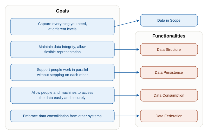
Data Structure: Defines the schema and the constraints that keep bad data out. Validation, uniqueness checks, referential integrity. Clear error messages.
Data Persistence: Stores the intent, answers questions about it, and keeps the complete history. Who changed what, when, and why. Roll back when needed.
Data Consumption: How people and systems actually get and use the data. APIs, web UI, CLI. Everyone gets access control suited to their role.
Data Federation: Pulls data in from the systems that already own it (Circuits DB, IPAM, etc.) and keeps it synced.
These four are not independent features; they stack. Data Structure decides what counts as valid. Data Persistence keeps the valid data, and its history, safe across concurrent writers. Data Consumption exposes it to everyone who needs it. Data Federation stops the SoT from becoming one more silo by deferring to the systems that are already authoritative.
Remove any one, and the others degrade. Without Data Structure, Data Consumption serves bad data. Without Data Persistence, there is no way to reason about what changed when something breaks. Without Data Federation, operators maintain the same data twice and the SoT loses their trust.
The first of the four belongs here, with the data, because it decides what the data is allowed to be. The remaining three are the subject of Chapter 5.
Data Structure#
Bad programmers worry about the code. Good programmers worry about data structures and their relationships.
Linus Torvalds
Network automation is as good as the data that sustains it. Wrong intent leads to broken networks, security breaches, and confused ops teams. The data structure, meaning the schema plus the constraints attached to it, is your guardian: it stops obviously wrong data from getting in and explains clearly why.
A schema does more than describe the shape of the data. It defines what valid means: which values are allowed, which fields are required, how objects relate to each other, and which constraints have to hold. That turns the schema into a contract: data that conforms to the schema can be trusted to satisfy the rules the schema expresses. Correctness is established once, at the boundary where data is written, instead of being rediscovered by every consumer downstream.
That distinction matters more than it sounds. Without the contract, every workflow that reads a device object has to defend itself: check that the management address is really an address, that the role is one it recognizes, that the site reference still resolves. Ten consumers means ten implementations of the same checks, drifting apart, each failing differently on the same bad record. With the contract, consumers do their job and trust their input. So encode as much of what you know about valid data into the schema as you reasonably can.
Four properties separate a schema you can live with from one you will fight:
Extensible. Existing models cover most of what you need but never all of it, and the model that fits today stops fitting when your next use case arrives. You need room to add fields and objects, plus a credible path to evolve and migrate existing data without losing it or breaking consumers. Extensibility, Polymorphism and Migrations goes into how.
Reusable. Model each thing once and reference it from everywhere it appears. An IP address belongs to an interface, which belongs to a device. That same address also turns up as a BGP neighbor address, a tunnel endpoint, and a service address. Nesting a fresh copy of the address structure inside each of those leaves you four definitions to keep consistent and no way to answer “where is 192.0.2.1 used?”. Define the address once as its own object and relate to it instead. How easy this is depends largely on your persistence choice: relational and graph stores make references natural, while document stores push you toward nesting and leave you maintaining the cross-references by hand (Querying Connected Data covers the trade-off).
Validatable. A schema that cannot reject anything is documentation. Constraints come in two flavors, and you need both:
- Structural validation asks whether the data matches the schema: correct types, required fields present, formats well-formed. Is
mgmt_ipan address, or the string"TBD"? - Semantic validation asks whether the data makes sense: prefixes that do not overlap, references that resolve, fields that are immutable once set, a VLAN ID inside the range this site actually uses.
Structural checks are cheap and local, because they can be decided from the record alone. Semantic checks are the ones that catch outages, and they cost more, because deciding them means consulting the rest of the data.
- Structural validation asks whether the data matches the schema: correct types, required fields present, formats well-formed. Is
Flexible. Every network has a standard and a set of controlled deviations. If the schema admits only the standard, the deviations do not disappear; they move somewhere you cannot see them. Say 70% of your sites fit one business-layer design and the remaining 30% carry small differences that recur: those exceptions should be expressible as patches on top of the standard, so the standard still applies everywhere it can. The same need shows up in the technical layer, where every interface type shares most attributes and each technology adds a few of its own. That is polymorphism, and it is covered below.
Schema Languages#
How you define your data matters. A schema language is what lets you state what valid means in a form a machine can check: the types, the required fields, the relationships, and the constraints. Several exist, no single one wins, and the right choice depends mostly on where your data already lives and who has to read it.
| Language | Best for | Strengths | Tradeoffs |
|---|---|---|---|
| SQL (DDL) | Data that already lives in a relational database | Mature, universally understood, and enforced by the database itself rather than by a separate step | Changing it means a migration, which makes fast-evolving models painful |
| JavaScript Object Notation (JSON) Schema | Validating documents and API payloads | Readable, excellent tooling, and composable: schemas can reference other schemas | format: ipv4 and friends exist but are annotations by default, so the validator has to be told to assert them |
| Yet Another Next Generation (YANG) | Device-facing models | Purpose-built for networks, and works directly with NETCONF, RESTCONF, and gNMI | Steep learning curve, heavy toolchain, and vendor models that disagree with each other |
| GraphQL (SDL) | Exposing one typed model to many different consumers | Strongly typed, doubles as the documentation, and lets each client fetch exactly the fields it needs | Requires a GraphQL layer in front of whatever actually stores the data |
| CUE | Keeping schema, validation, and generation in one place | Validates and generates from the same definitions, with invariants enforced rather than documented | Small ecosystem, and unfamiliar to most network teams |
Two notes before moving on. First, the serialization format (YAML, JSON, XML, Protocol Buffers) is a separate decision from the schema language, and the two get conflated constantly. YAML is pleasant to read and validates nothing by itself. Second, most SoT products do not hand you a raw schema language at all; they expose their own modeling layer and generate the rest. That is usually a feature, as long as you can still answer what the model allows and how you change it.
Picking a language settles what you can express. Enforcement is what you do with it: turning those constraints into checks that run on every write, so the contract above actually holds.
Schema and Constraint Enforcement#
The validation types below span both flavors introduced earlier. Schema and range validation are structural: they can be decided by looking at the record alone. Uniqueness, referential integrity, and business rules are semantic: deciding them means consulting the rest of the data.
| Validation Type | Example Rules | Example Error |
|---|---|---|
| Schema Validation Enforce data types and formats | VLAN id: integer 1-4094 VLAN name: string, max 32 chars VLAN sites: array of site references VLAN status: enum(active, planned, deprecated) | { "id": 5000, "name": "CUSTOMER-VLAN" }→ Error: VLAN ID 5000 exceeds maximum 4094 |
| Uniqueness Constraints Prevent duplicate entries | VLAN 100: unique per site IP 192.0.2.1: unique across IPAM Hostname “pe-01”: unique per region | Attempt to create second “pe-01” in same region → Error: Hostname already exists |
| Referential Integrity Ensure relationships remain valid | Circuit references: site_a, site_b (must exist in Sites), vendor (must exist in Vendors) | Delete site_a referenced by circuit → Options: Reject deletion, Cascade delete, or Orphan with “site unknown” |
| Range Validation Enforce numeric and pattern constraints | BGP AS: 1-4294967295 IPv4: format: ipv4, not a hand-rolled ^(\d{1,3}\.){3}\d{1,3}$, which accepts 999.999.999.999Interface speed: {1G, 10G, 25G, 40G, 100G} | Interface speed “5G” → Error: Invalid speed, must be one of {1G, 10G, 25G, 40G, 100G} |
| Business Rule Validation Enforce organizational policies | If VLAN status=‘active’ → must have ≥1 site If device type=‘firewall’ → must have security_zone If service type=‘L3VPN’ → route_distinguisher must be unique per VRF | Active VLAN with no sites → Error: Active VLANs must be assigned to at least one site |
For example, using JSON Schema, you can validate your JSON (or YAML) data. This is a JSON Schema that defines a few attributes for a device:
{
  "$schema": "https://json-schema.org/draft/2020-12/schema",
  "type": "object",
  "required": ["hostname", "mgmt_ip", "interfaces"],
  "additionalProperties": false,
  "properties": {
    "hostname": {
      "type": "string",
      "pattern": "^[a-z0-9-]+$"
    },
    "mgmt_ip": {
      "type": "string",
      "oneOf": [
        { "format": "ipv4" },
        { "format": "ipv6" }
      ]
    },
    "interfaces": {
      "type": "array",
      "minItems": 1,
      "items": {
        "type": "object",
        "required": ["name", "enabled", "vlan"],
        "additionalProperties": false,
        "properties": {
          "name": {
            "type": "string",
            "pattern": "^Ethernet[0-9]+$"
          },
          "enabled": {
            "type": "boolean"
          },
          "vlan": {
            "type": "integer",
            "minimum": 1,
            "maximum": 4094
          }
        }
      }
    }
  }
}Those two constraints are the opening story’s missing rules, in the form a machine can enforce: vlan is an integer bounded at 4094, and mgmt_ip has to be an address in either family rather than any string shaped like one.
And this is a concrete device record that conforms to the schema above:
{
  "hostname": "sw-core-01",
  "mgmt_ip": "192.0.2.10",
  "interfaces": [
    {
      "name": "Ethernet1",
      "enabled": true,
      "vlan": 100
    },
    {
      "name": "Ethernet2",
      "enabled": false,
      "vlan": 200
    }
  ]
}My advice: reject bad data. I’ve seen too many “soft validation” systems turn into garbage dumps because “just this once” becomes standard operating procedure. If it’s important enough to validate, it’s important enough to enforce.
But, as usual, there are exceptions. The following situations may justify relaxing the validation posture:
Policy guidelines (not rules): “You’re using a /22 subnet when we usually use /24” is a warning, not an error. Warn the user, log it, but let them proceed if they confirm the override.
Expensive cross-object checks: If validation takes more than a few seconds, accept the change and validate asynchronously. But still enforce the result: flag the violation, notify the user, and require fixes.
Brownfield network discovery: When you’re importing existing configurations, you’ll find violations everywhere. Flag them, but don’t block import. The whole point is to discover what’s actually there, even if it violates your ideal model.
Everything else? Reject it. Your automation depends on trustworthy data. Bad data means outages.
However, validation is not free. A hierarchy of validation costs affects design decisions. Practical systems choose a performance target and validate only to that level for synchronous write paths:
| Approach | Latency budget | Advantages | Disadvantages | Best For |
|---|---|---|---|---|
| Synchronous Validation (validate before accepting write) | Fast path < 10ms: types, regex, local index Standard path < 100ms: uniqueness, referential integrity | • User gets immediate feedback • Data consistency guaranteed | • Slow API responses (validation latency) • Blocks high-throughput automation | Critical data integrity operations Interactive user workflows |
| Asynchronous Validation (accept first, validate later) | Deferred, seconds to hours: background consistency checks | • Fast API responses • High throughput | • Data consistency window exists • Complex error reporting (“write succeeded but failed validation 5 minutes later”) | Bulk operations High-volume automation |
| Hybrid Approach | < 100ms inline, slow path < 5s or deferred: rule engines, complex business logic | • Fast type/format validation synchronously • Expensive cross-object validation asynchronously • API endpoint to check validation status | • More complex implementation • Requires status tracking | Most production systems Balanced performance and correctness |
Also within the validation context, machine learning can catch what rules cannot: not whether a value is legal, but whether it is unusual. Three patterns show up in practice. Anomaly detection compares a change against historical ones and questions the outlier: branch VLANs have always landed in 1000-1999, so a request for 2500 earns a confirmation step rather than a rejection. Auto-correction proposes the likely intent behind an invalid value, offering /24 for a typed /33 because every other subnet at that site is a /24. Embedding comparison flags a device whose configuration diverges from its peers in the same role, catching the NTP server somebody forgot.
All three are suggestions, not gates, and that distinction is the whole design. Surface only high-confidence findings or you manufacture alert fatigue; always show the pattern that triggered the flag, because an operator who cannot see the reasoning will not trust the tool twice; and let people mark false positives, which is both courteous and how the model improves. Confidence scores matter here for the same reason: they tell the reader how much weight to give a recommendation that nobody is obliged to follow.
After the validation sections, let’s explore how to make it extensible.
Extensibility, Polymorphism and Migrations#
Products sit on a spectrum. At one end are opinionated built-in models out of the box: fast to deploy, decisions already made, and painful when your network does not fit the mould. At the other are fully custom models, a perfect fit with no wasted fields, bought with design time, trial and error, and nobody else’s work to copy (which is why those products ship opinionated models to start from anyway).
Start opinionated. I do not care how special you think your network is: the teams who set out to build their own perfect model are still modeling two years later, while the ones who adopted an existing model shipped something valid months ago. You are probably not building a hyperscale cloud. Use what exists, extend it when you hit a real limit rather than an imagined one, and ship.
Which makes extensibility the decision that actually matters. If tracking a new “cost center” field means rebuilding the schema, walk away; if it is a custom attribute you add in twenty minutes, you have the right tool. Aim for 80% standardization with 20% room for your own reality, and treat “infinitely flexible” as a warning: it usually means infinite configuration before anything works.
Many data models are similar, but not exactly the same. That leaves you two obvious options, both bad: overload one model with fields that only apply to a subset of its objects, or create several specific models that are then hard to connect. The way out is polymorphism: one model, many flavors.
All interfaces aren’t created equal. A physical optical port and a tunnel interface share some properties, but they’re different beasts. You could create completely separate models for each, but that gets messy fast and limits usability.
Better approach: define a shared base model that covers what they have in common, then create specialized variants for the details that differ.
# All interfaces share these basics
interfaces:
  - name: "eth0"
    type: "physical"
    status: "up"
    mtu: 1500
    ipv4_address: "192.0.2.1/24"

# But a physical optical port has extra stuff
  - name: "eth49"
    type: "physical_optical"
    status: "up"
    mtu: 1500
    ipv4_address: "192.0.2.1/24"
    optics_module: "100GBASE-LR4"
    tx_power_dbm: -2.5
    rx_power_dbm: -8.3
    laser_temperature: 48.2

# And a tunnel looks totally different underneath the covers
  - name: "tun-vpn-dallas"
    type: "tunnel_gre"
    status: "up"
    mtu: 1476
    ipv4_address: "10.0.0.1/30"
    tunnel_source: "203.0.113.1"
    tunnel_destination: "198.51.100.5"
    tunnel_encap: "GRE"
tunnel_key: 100This way, your scripts can query “all interfaces on this device” without knowing whether they’re talking to optics or tunnels, because the shared fields are common to both. But when you need optical-specific details (getting TX power readings), you can reach into those specialized fields. Add a new interface type down the road? No problem: just add another variant.
Last, extensibility also applies to the lifecycle of the models themselves. Models change, so plan for it.
Networks live for decades. Your model won’t stay static. You’ll add new fields, change how things relate to each other, deprecate stuff that doesn’t work anymore. But you can’t just flip a switch and break everything running on your old schema.
The challenge is that when your model changes, a lot of downstream stuff can break: validators need new rules, APIs change what they return, database queries assume certain columns exist, your templates need different field paths, reports are written against the old structure. All of that needs to adapt, or at least not catastrophically break. Here’s how to handle changes without blowing things up:
Mark things as deprecated before you remove them. If a field is going away, tell everyone 2-3 releases ahead of time. Give them a grace period to migrate.
Support field aliases during the transition. Old code asking for
device_name? Route it tohostnameunder the hood. Your API still works, people have time to update their automation.Create migration helpers. When you restructure data (like moving interfaces from a flat list to nested under devices), provide scripts that do the legwork.
Test with everything that depends on your data. Before rolling out schema changes:
- Does the API still return data the old way? (via aliases)
- Do your templates still render?
- Do the SQL queries still work?
- Do integrations with external systems still parse what they get?
Expect mixed versions in production for a while. Big organizations often have devices on three different schema versions simultaneously:
150 devices on schema 1.9 (old)
300 devices on schema 2.0 (current)
50 devices on schema 2.1 (beta testing)
Your system needs to handle all three without breaking. That complexity is worth it: networks matter too much to break with careless schema changes.
Data structure is fundamental to managing data, but sooner or later that data has to become durable, and that is where Chapter 5 picks up. Before it, one question decides what your data looks like on day one: where it comes from when the network already exists.
Brownfield Onboarding#
When you deploy a source of truth in an existing network, you face a tricky problem: how do you populate it with current state without just embedding all your legacy cruft as permanent truth?
The wrong approach: Poll your devices and assume “whatever is running = what should be”. You’ll load all workarounds, hacks, and technical debt straight into the source of truth.
The right approach: Use the current network state as a starting point, not as the truth. Snapshot it, load it in, then deliberately redesign it until it describes what you actually want. From that point on, the source of truth leads and the network follows.
Here’s what that looks like in practice:
Bootstrap: Take a snapshot of your current network (devices, IPs, VLANs, circuits) and load it into the source of truth as starting data. You may use the state from a CMDB if it is accurately populated (something I have never seen with my own eyes yet).
Redesign: Over weeks and months, have people review that data and decide what the intended state should actually be. You’ll probably want to consolidate redundant VLANs, clean up legacy stuff, standardize naming, and write the design templates for future deployments.
Flip the direction: Once you’ve got the design you want, stop syncing from the network back to the source of truth. Now the source of truth is the boss. Execution (Chapter 6) pushes changes outward to the network.
Detect drift: Observability (Chapter 7) watches for devices that drift from what the source of truth says they should be. When drift happens, operators decide: fix the device or fix the source of truth?
You don’t need to build this from scratch. There are tools built specifically for this problem.
This approach requires initial effort but avoids the trap of treating deployed state as permanent truth. Your SoT evolves toward clean design intent, even if the network takes time to fully align. Obviously, you can keep using it in dry-run mode to double-check that the network has not drifted.
Be clear about what the snapshot buys you, though. It gets you a starting point. It does nothing to keep the data true six months later, when somebody reassigns an address during an incident and tells nobody. Keeping intent and reality aligned after go-live is reconciliation, and Chapter 5 covers it.
With the data modeled, validated, and loaded, it is worth seeing all three layers at work on one real network.
Implementation Example#
We return to the campus network from Chapter 3: roughly 800 access and distribution switches from three different vendors, spread across six buildings, A through F, carrying a steady stream of service requests for new VLANs, subnet assignments, routing policy updates, and access control changes.
Three systems already hold a piece of the picture, and none of them holds the whole thing:
- An IPAM, authoritative for address allocation, prefixes, and DNS across every campus subnet.
- An asset DB, authoritative for switch locations, hardware models, building assignments, and maintenance history.
- The switches themselves, carrying the only record of what is actually deployed, spread across 800 devices with no consolidated view.
The problem. When the application team asks for a new VLAN, an engineer cross-references the IPAM for a free subnet, the asset DB for which switches sit in the target building, and a handful of Secure Shell (SSH) sessions to see which VLANs are already there. Nothing records what the intended state of each switch should be, so Configuration Drift accumulates unnoticed, and adding a design for a new vendor means editing documentation in three places and hoping they stay consistent.
Requirements:
- Let the requester describe the service, not the implementation: no VLAN IDs, no prefixes, no switch lists
- Derive every technical value from that description, so there is no field in which an operator can mistype one
- Validate structure once, at the write boundary, rather than in every consumer downstream
- Keep the technical layer vendor-agnostic, so a new platform means a new template and not a new model
- Record what is intended separately from what is deployed, and be able to compare them
- Carry the data that already lives in the IPAM and the asset DB without copying it
The approach. The IPAM and the asset DB are already part of this campus’s Source of Truth; what is missing is the piece that joins them and models the network itself. Add a central SoT: it joins the two existing sources rather than replacing them, and contributes the one thing neither of them has: the network model. VLAN definitions, per-vendor templates, the design patterns for the access and distribution layers, and the service-request model that turns a business request into the technical objects the Executor needs. Joining several authoritative systems into one view has a name, federation, and Chapter 5 is where it gets defined and built.
This example names no products on purpose. Several platforms could play each role here, and naming them would date the chapter faster than it would help you. What transfers is the shape of the solution: which data sits at which layer, and what the layers look like once there is a real network behind them. Chapter 5 returns to this same campus for the rest of the architecture.
Let us follow one real request that the source of truth has to implement, and look at the actual data at each step. The request is ordinary: the application team wants a new VLAN called app-payments in Building B.
One Request Through the Layers#
The business layer: what the operator types
Everything the operator provides is this:
vlan_service:
  name: app-payments
  building: B
profile: standardThree fields. Not a VLAN ID, not a prefix, not a list of switches. Those are all derivable, and anything derivable is something an operator can get wrong.
What makes them derivable is a set of expansion rules (transformations) you write once:
profiles:
  - name: standard
    mask_length: 24
    qos_class: af21
    applies_to_roles: [access, distribution]
  - name: high-security
    mask_length: 26
    qos_class: af31
    applies_to_roles: [access]
requires_acl: truePlus the rules that consume them: the service name must match ^[a-z][a-z0-9-]{2,15}$; the VLAN ID is the next free one in the range reserved for that building; the prefix is carved from the building supernet at the profile’s mask length; the service applies to every switch in the building whose role appears in applies_to_roles.
Notice what this buys you beyond brevity. There is no field in which an operator can type a /26 for a standard service, because the mask comes from the profile. This is the guardrail-for-free property from the Business Layer section, made concrete.
The technical layer: what the expansion produces
vlans:
  - name: app-payments
    vlan_id: 412
    building: B
    prefix: 10.12.4.0/24
    qos_class: af21
    gateway:
      address: 10.12.4.1
      mask: 24
    switches:
      - { name: sw-b-acc-01, role: access,       platform: vendor-a }
      - { name: sw-b-acc-02, role: access,       platform: vendor-a }
- { name: sw-b-dst-01, role: distribution, platform: vendor-b }This is vendor-agnostic on purpose. platform records which vendor a switch is, but nothing about how that vendor expresses a VLAN leaks into this layer. That is the constraint from the Technical Layer section: the same expanded record has to survive a vendor swap. The listing shows three of Building B’s switches, on two of the campus’s three platforms. A Vendor C switch joins the same record with a different platform value, and nothing else changes.
The component layer: what reaches the device
Now, and only now, the data meets platform syntax:
{% for sw in vlan.switches if sw.platform == "vendor-b" %}
! ===== {{ sw.name }} =====
vlan {{ vlan.vlan_id }}
  name {{ vlan.name | upper }}
{% if sw.role == "distribution" %}
interface Vlan{{ vlan.vlan_id }}
  description {{ vlan.name }} gateway
  ip address {{ vlan.gateway.address }} {{ vlan.gateway.mask | to_netmask }}
  mtu 9216
  service-policy input QOS-{{ vlan.qos_class | upper }}-IN
{% endif %}
{% endfor %}Note the filter on the loop. This template renders one platform, and there is a second template for Vendor A, selected by that same platform field, producing different syntax from this identical record. That is what keeping the technical layer agnostic buys: onboarding a vendor adds a template, not a data model.
Two details worth pausing on. to_netmask is a filter you supply, not something Jinja ships; every real template library grows a handful of these for address arithmetic. And mtu 9216 is hardcoded, which is the invariant exception from the Component Layer section: the campus standardized on jumbo frames everywhere, so the value lives in the design rather than as a field on 800 objects.
Rendering for sw-b-dst-01 gives the configuration artifact the Executor will deploy:
! ===== sw-b-dst-01 =====
vlan 412
  name APP-PAYMENTS
interface Vlan412
  description app-payments gateway
  ip address 10.12.4.1 255.255.255.0
  mtu 9216
service-policy input QOS-AF21-INThat is the whole path, from three fields an operator typed to the lines one switch will run. One question is left: how much of that path the schema can actually protect.
What the Schema Catches, and What It Does Not#
The VLAN service object gets a schema, and the reusable pieces are referenced rather than inlined:
{
  "$id": "https://example.net/schemas/vlan-service.json",
  "title": "VlanService",
  "type": "object",
  "required": ["name", "vlan_id", "building", "prefix", "gateway"],
  "additionalProperties": false,
  "properties": {
    "name":      { "type": "string", "pattern": "^[a-z][a-z0-9-]{2,15}$" },
    "vlan_id":   { "type": "integer", "minimum": 1, "maximum": 4094 },
    "building":  { "type": "string" },
    "qos_class": { "type": "string", "enum": ["af21", "af31", "ef"] },
    "prefix":    { "$ref": "prefix.json" },
    "gateway":   { "$ref": "ip-address.json" },
    "switches":  { "type": "array", "items": { "$ref": "device-ref.json" } }
  }
}ip-address.json is defined once and referenced from here, from BGP neighbors, from tunnel endpoints, and from device management addresses. That is the reusability property: one definition of what an address is, and a single place to ask where a given address is used. device-ref.json does the same job for the switch references.
Note what the schema does not mention. additionalProperties: false means anything not listed here is rejected, so _version and _metadata, the fields the store attaches to every record, have to sit outside the validated document. Chapter 5 shows them on the stored object. They are written by the store rather than by whoever authored the intent, and keeping them out of the schema is what stops a client from forging them.
The more instructive part is what this schema cannot express. It will reject vlan_id: 5000 and the name App_Payments, but it will not catch any of these:
- whether VLAN 412 is already in use in Building B
- whether
10.12.4.0/24sits outside Building B’s supernet - a gateway of
10.12.5.1, which is a valid address but not inside this service’s prefix
Those are the semantic checks from Data Structure, and each one needs to consult other records to decide. Structural validation lives in the schema; semantic validation lives in the SoT’s own rules, and it is the second group that prevents outages.
Notice which half of that distinction the opening story sat in. A VLAN ID of 4192 and an address of 10.2.30.283 are the first kind: the schema rejects both the moment somebody tries to save, and three switch parsers only had to do that job because neither field had a type. The three cases above are the second kind. They are no harder to express, but the SoT has to consult the rest of the data before it can tell you no, and that is a design decision rather than a line of schema.
Getting Started#
Reading about intent data is easy. The first week of modeling it is where people stall, usually because the design decisions arrive all at once. The data decisions reduce to three steps, roughly in this order.
Pick the objects you need. Work backwards from your configuration artifacts: every value that varies across devices has to come from somewhere, and that somewhere is an object in your model. Device, site, prefix, VLAN, circuit, policy is a reasonable starting set for most networks. Anything that does not vary can be hardcoded in a template and is still part of your intent.
Model them, but do not start from a blank page. Good network models already exist; adopt one and adapt it. For each object settle three things: what it contains (fields, types, what is required), how it relates to the others (references, ownership), and what makes a value invalid. You will revise all three, which is why the schema has to be extensible from day one.
Choose how high-level the entry point should be. You can defer the business layer, but settle early whether you are heading there, because it shapes the technical model underneath it. Teams that bolt abstraction on afterwards usually find their technical layer encoded assumptions that the abstraction now has to fight.
If you are starting in a brownfield network, and nearly everyone is, take a snapshot of the current state first to give yourself a starting point. Brownfield Onboarding covers why that snapshot is a starting point and not the truth.
Those three get you modeling. Three more follow, and all of them belong to the system around the data: how it is reached, who owns each value, and making something real depend on it. Chapter 5 has them, and it closes this same campus example with the architecture all of it adds up to.
Summary#
The two typos in the opening story were not preventable. Somebody will always enter the wrong digit. What cost that team its maintenance window is that the digits survived every step between the form and the device: two fields with no type, a review with nothing to review against, and a template whose only job is substitution. This chapter has two answers, and the second is the better one. Give the data a shape that makes those values unsaveable, then stop asking people for values you can derive.
It starts with agreeing on what data is in scope, at three levels of abstraction. The technical layer holds the vendor-agnostic model of what the network is made of. The business layer sits above it, taking a short request (“a payments VLAN in Building B”) and expanding it into that technical detail through rules you wrote once, which is what makes the guardrails automatic rather than reviewed. The component layer sits below, rendering the agnostic model into the per-device artifact each platform actually accepts, whether that code runs next to the data or inside an Executor module. You do not always need all three, but you should know which ones you are building.
Then the data needs a shape you can trust. Data Structure makes the schema a contract, so correctness is established once at the write boundary instead of being re-checked by every consumer downstream. Structural validation lives in the schema; the semantic rules that actually prevent outages live alongside it and cost more, because deciding them means consulting the rest of the data. The worked example showed the split: the schema rejects vlan_id: 5000 on its own, and nothing in it can tell you that VLAN 412 is already taken in Building B.
One more thing decides whether any of this survives contact with a real network. In a brownfield network, and nearly every network is brownfield, your starting data is a snapshot of what exists rather than a statement of what should exist. Load the snapshot, redesign it deliberately, then flip the direction and let the data lead.
Chapter 5 turns this data into a system: how intent survives concurrent change, how every consumer reaches it, and which system decides each value when three of them hold a copy.
References#
- Network Programmability and Automation, 2nd Edition, Matt Oswalt, Christian Adell, Scott S. Lowe, and Jason Edelman (O’Reilly, 2023). Foundational concepts for network automation, including how source-of-truth data drives configuration generation.
- Network Programmability with YANG, Benoit Claise, Joe Clarke, and Jan Lindblad (Addison-Wesley, 2019). The definitive reference on YANG data modeling and how IETF and OpenConfig models are structured, read, and written.
- Infrastructure as Code, 2nd Edition, Kief Morris (O’Reilly, 2021). Treating infrastructure definitions as versioned, testable code; the basis for the design-as-code and versioned-design practices in this chapter.
💬 Found something to improve? Send feedback for this chapter